Laser Line Scanning Process
Laser line scanning is a non-contact method of capturing the shape of a 3 Dimensional object. This is often referred to as creating a “digital copy”. The digital copy of the object can be used for reverse engineering or computer-aided inspection. Laser line probes create the digital copy by measuring the distance from the scanner to the laser beam that is projected onto the object. A triangulation method is used to do this. A camera picks up the laser on the surface at a known angle to determine the distance. The laser line profile will change as it wraps around 3D geometry. It is called triangulation because the laser emitter, camera, and laser points projected onto the object form a triangle. Since the distance between the emitter and the camera is known and the angle of the emitter is known, the angle of the camera corner of the triangle can be determined by locating the laser line point in the camera’s field of view. One laser line contains hundreds of laser points. These points form what is know as a point cloud.
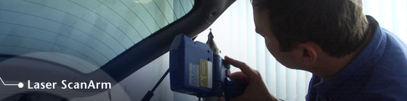
Laser line probes are normally mounted onto an articulating arm so that the location of the actual scanner is known at all times. Arms come in 6 or 7 axis designs and have high precision encoders and temperature sensors in every joint. Articulating arms know where they are located and at what angle to within about .001”. Because of this, the individual laser scans are already positioned correctly in the computer software. Laser line probes that are not mounted on an arm must use a turntable that can measure the amount of rotation, or the individual scans must be positioned and aligned in a point cloud registration software package such as RapidForm or Geomagic.
Surface properties can affect the laser scanning process. Shiny surfaces will reflect the laser too much causing what is known as “noise”. Noise in the laser scanning process is when the camera measures laser points that are not actually on the part surface. Shiny surface can also cause double images in the scan data. Dark surfaces are also difficult to scan because they tend to absorb the laser light making it impossible for the camera to see. Dark surfaces can be coated with a white powder or spray to alleviate the problem. An additional geometry concern is sharp edges that cause the laser beam to “ricochet” and create false geometry. Skilled operators know how to adjust the laser settings and scanning angles to reduce the problem.
Laser line scanning is only one of several types of 3D scanning processes. Other processes include structured light, modulated light, time of flight, and computed topography. All have their advantages and disadvantages. A good service bureau should be able to point you in the right direction.